Trade Members Get 10% Off. Sign Up Today
How to Solder LED Strip Lights Professionally
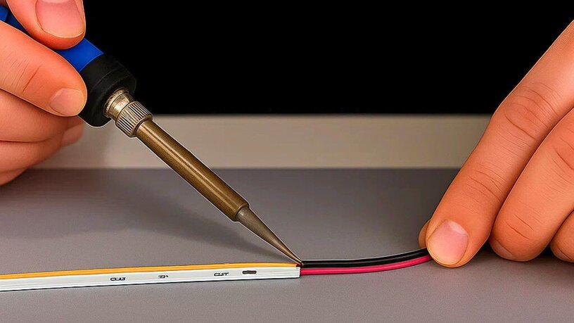
Learning how to solder correctly in a lighting installation is essential for delivering a clean, reliable finish.
Whether working with LED tape, profile channels, joinery details, or architectural systems, professional soldering ensures a stable connection that performs over time.
This guide outlines the process for soldering LED tape using Ultra LEDs’ recommended tools and materials. It focuses on durability, consistency, and electrical reliability across any project.
Understanding LED Strip Construction
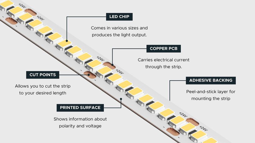
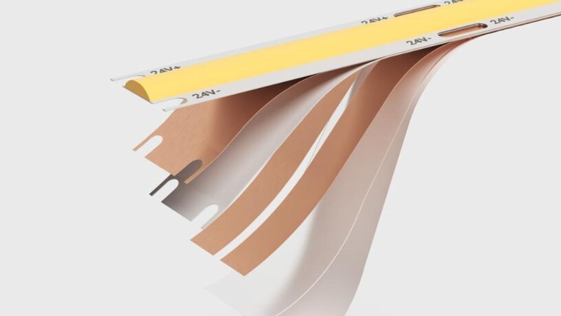
Before soldering, it is important to understand how LED tape is built and how polarity works.
Pad layout
- Single colour: + (24V or 12V) and –
- RGB: + (common anode) and R, G, B –
- RGBW: + and R, G, B, W –
Always check the printed pad labels. Pad order can vary between models.
Coatings
Many IP-rated LED strips are coated with silicone or PU. Remove the coating carefully over the pad area only to avoid damage to the copper tracks.
Key risks
- Overheating can lift pads or damage the phosphor layer.
- Solder bridging can short adjacent pads.
Tools and Materials
The following tools and materials are recommended for reliable soldering and connection of Ultra LEDs tape systems.
| Tool / Material | Specification / Notes |
|---|---|
| Temperature-controlled soldering iron | 60–80W rating |
| Soldering tip | 2–3mm chisel tip, kept clean and tinned |
| Rosin-core solder | Lead-free Sn99/Cu0.7 or Sn63/Pb37 (where permitted) |
| Flux | No-clean liquid or gel type |
| Flexible wire | Fine-stranded, 22–24AWG for short runs, 18–20AWG for higher load |
| Heat shrink tubing | 2:1 or 3:1 ratio |
| Cleaning | IPA wipes for residue removal |
| Supporting tools | Helping hands, clamps, side cutters, and a multimetre |
Professional Soldering Process
1. Prepare the workspace
- Disconnect power and confirm 0V with a multimetre.
- Work on a clean, stable surface with fume extraction.
- Cut only at printed cut lines.
2. Expose and clean the pads
- If coated, score gently around the pad and remove the layer cleanly.
- Wipe with IPA to remove residue or light oxidation.
- Avoid scratching copper pads.
3. Tin the pads and wires
- Apply a small amount of flux to each pad.
- Heat briefly and add solder until covered.
- Strip 2–3mm of wire, twist strands, and pre-tin until smooth and bright.
Checkpoint: Pads and wires should have even, shiny solder films with no spikes or buildup.
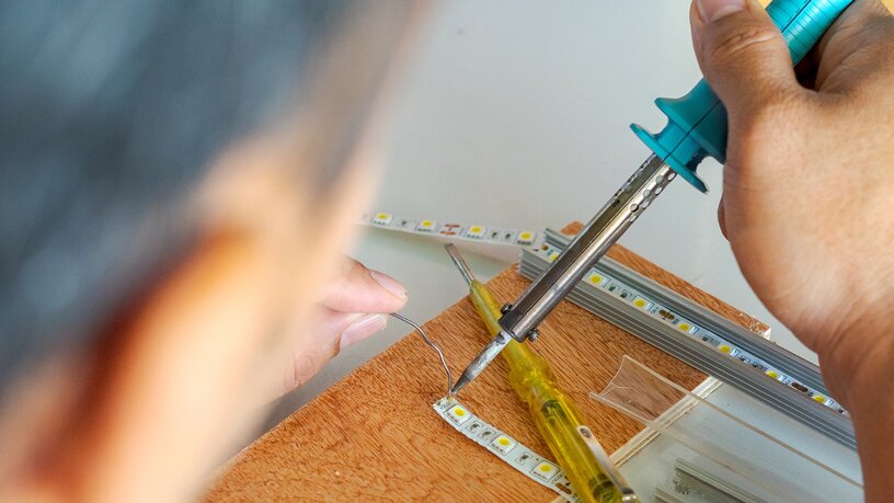
4. Make the joint
- Align each wire with the correct pad.
- Touch the iron to the joint for one to two seconds until the solder flows evenly.
- Hold still while it cools.
- A good joint is flat, bright, and firmly bonded.
5. Insulate and add strain relief
- Inspect for solder bridges or stray strands.
- Slide heat shrink over the joint and apply heat evenly.
- In joinery or profile work, secure the cable to prevent stress on pads.
6. Clean and test
- Remove flux residue with IPA.
- Check continuity and polarity with a multimetre.
- Power on gradually and confirm that all sections light evenly.
Common Issues and Fixes
Cold joints
If solder looks dull or uneven, both pad and wire may not have heated evenly. Reheat gently until the solder flows smoothly.
Bridging
If pads short together, remove excess solder using a solder wick or desoldering braid.
Pad lift
Pads can detach when overheated or moved while cooling. Use a lower temperature and let joints cool naturally.
Wrong polarity
If the strip doesn’t light or LEDs are damaged, check polarity before soldering.
Joint strain
If joints break under tension, add strain relief or heat shrink tubing to stabilise the connection.
Testing and Troubleshooting
- Visual check: Joints should be smooth, bright, and level.
- Continuity test: Confirm correct polarity and channel output.
- Voltage check: Measure under load, expecting approximately 24V.
- Repair: If a pad is damaged, bridge to the next intact pad using a short jumper wire.
FAQs
Can LED strips be re-soldered?
LED strips can be re-soldered when fully powered off. The pads should be cleaned, re-tinned, and inspected for damage before applying new solder to ensure a strong, conductive joint.
Is soldering better than using connectors?
Soldering is generally better than using clip-on connectors for permanent or high-density installations. It produces smaller, neater joints with stronger contact and lower risk of long-term failure.
How long should soldering take?
A solder joint should take less than five seconds of contact time. Prolonged heating can lift pads or damage the phosphor layer on the strip.
What size heat shrink should be used?
Heat shrink tubing between 3mm and 6mm in diameter is suitable for most LED solder joints. It should slide easily over the connection before heating and contract firmly once applied.
Can poor soldering cause flicker?
Poor soldering can cause flicker, dimming, or intermittent failure. Weak or cold joints create unstable electrical contact, leading to visible inconsistencies in light output over time.
Get in touch with Ultra LEDs today
Planning your next lighting install? Explore Ultra LEDs’ full range of drivers, LED strips, and accessories — built to deliver reliable, professional results across commercial and display projects.


